3D settings for 3D bodies
- Creating 3D objects
- Creating 3D bodies
- Producing 3D shapes
- Editing 3D objects
- 3D settings for 3D bodies
- Dialog page - Geometry
- Dialog page - Shading
- Dialog page - Illumination
- Dialog page - Textures
- Dialog page - Material
- 3D settings for 3D shapes
- Combining objects in 3D scenes
- Examples for your own experiments
3D Effects dialog – general buttons
The 3D Effects dialog offers a wide range of possible settings for 3D objects produced with variations 1 to 3 (see previous sections). To open the dialog, right-click on such a 3D object and choose 3D Effects from the pop-up menu. You can also activate a 3D Effects icon ![]() on the Standard toolbar or add it to another toolbar using Customize Toolbar > Add > Category Options > 3D Effects.
on the Standard toolbar or add it to another toolbar using Customize Toolbar > Add > Category Options > 3D Effects.
The dialog can be docked in a similar manner to the Navigator or Template windows.
The possible settings are arranged in various thematic categories. The buttons at the top of the window serve to bring up the appropriate dialog pages. In order to apply the settings you have altered on a dialog page it is necessary to click the Assign [[Image:]] button. This will apply all the changes you have made – on the current as well as on other pages of the dialog window – to the object.

Figure 11: Upper part of the 3D Effects dialog
So that the Effects dialog can take over all the current properties of the object, you must click the ![]() button. If you deactivate this button before you leave an object and click on it again when you open the Effects dialog for another object, the settings are carried over from the first object to the second object. You can use this as a sort of a transfer of “favorite” settings from one object to another as all the settings are brought over to the other object. In normal use, however, the icon should be left activated.
button. If you deactivate this button before you leave an object and click on it again when you open the Effects dialog for another object, the settings are carried over from the first object to the second object. You can use this as a sort of a transfer of “favorite” settings from one object to another as all the settings are brought over to the other object. In normal use, however, the icon should be left activated.
In the lower area of the dialog you will find another row of buttons (see Figure 12), which are available on each page of the dialog.
![]()
Figure 12: Buttons for geometric transformations
The first two buttons correspond to the menu commands Modify > Convert > To 3D / To 3D Rotation Object. When the dialog for a 3D object is called up, these buttons are inactive. The third icon switches on or off a perspective view of the object.
| Converts the selected 2D object to an extrusion body. | |
| Converts the selected 2D object to a rotation body. | |
| Switches between a central projection and a perspective projection. |
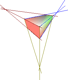
With a central projection parallel edges are shown as meeting at some common point in the distance, as shown on the button symbol. Parallel projection retains all parallel edges as parallel, as is often used to produce oblique figures in school. The switching process is carried out on the entire 3D scene.
With central projection (see Figure 13) Draw produces the object with three vanishing points. The parameters for central projection are set indirectly through the camera settings on the dialog page Shading.

Figure 13: Figure shown using central projection. For clarity the projection lines have been added.
| Content on this page is licensed under the Creative Common Attribution 3.0 license (CC-BY). |