The following examples start from a filled circle. As mentioned earlier, in order to use Edit Points mode, you first need to convert the object to a curve.
You will notice that after conversion, the handles located in the corners of the rectangle have disappeared. This behavior is normal in that the handles which are used in Edit Points mode are located along the outline or trace of the drawn object.
 Figure 18: Moving a junction point. |
The Move Points button  is the default mode when editing points. If it has not been activated, click on the button. When this mode is active, the mouse cursor has the following shape when it is hovered over an edit point: is the default mode when editing points. If it has not been activated, click on the button. When this mode is active, the mouse cursor has the following shape when it is hovered over an edit point:

Movement of a point is one of the easiest manipulations to do. Figure 18 illustrates how an egg can be drawn very easily by starting from a circle and dragging the the top point upwards.
|
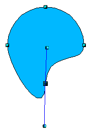 Figure 19: Rotating a tangent. |
To change the direction or location of the tangents, move the circular handles at each end. The mouse cursor then looks like this:

|
 Figure 20: Adding an edit point to a curve. |
Use the Add Points button  to add an extra edit point to an existing curve. Click on the curve at the spot where you want to insert a point and then move the mouse slightly, in any direction, while holding down the button. Watch out! If you just click, the new point will not be added. to add an extra edit point to an existing curve. Click on the curve at the spot where you want to insert a point and then move the mouse slightly, in any direction, while holding down the button. Watch out! If you just click, the new point will not be added.
The tangent attributes associated with the new point depend on the buttons that are selected on the toolbar.
|
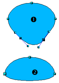 Figure 21: Deleting points from a curve. |
The Delete Points button  has the opposite effect: it subtracts one or more points from the curve. The resulting curve stretches itself automatically around the remaining points after subtraction. has the opposite effect: it subtracts one or more points from the curve. The resulting curve stretches itself automatically around the remaining points after subtraction.
Select one or more points to delete. You can select several points by holding down the Shift key (➊).
When you have selected the points you want to delete, click the Delete Points  button. The selected points disappear from the curve, which then reforms around the remaining points (➋). button. The selected points disappear from the curve, which then reforms around the remaining points (➋).
You can also delete the selected points by pressing the Del key on the keyboard.
|
 Figure 22: Cutting a curve. |
Use the Split Curve button  to split or cut a curve at the location of the selected handle. If the object is filled, it will be emptied, because the curve that represented the edge is no longer closed. to split or cut a curve at the location of the selected handle. If the object is filled, it will be emptied, because the curve that represented the edge is no longer closed.
Check that you have selected the correct handle (➊), click the Split Curve button  (➋) and notice that the object is no longer filled. You can then check, by moving the point, that the curve has indeed been separated (➌). (➋) and notice that the object is no longer filled. You can then check, by moving the point, that the curve has indeed been separated (➌).
If you have an open curve, the start point of the curve is larger than the others.
|
 Figure 23: Moving a segment. |
You can also separate a curve at several points simultaneously. Just keep the Shift key pressed down and select all of the points at which the cut should occur.
Drag and drop segments with the mouse to move them from the original curve.
|
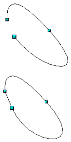 Figure 24: Closing an open curve. |
To close an existing curve, select an open curve and click on the Close Bézier button  . .
The opening point is identified by a slightly larger handle.
|
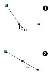 Figure 25: Using the “select points” switch. |
The Select button  on the Drawing Toolbar functions as a switch. It works as follows. on the Drawing Toolbar functions as a switch. It works as follows.
If you have two points linked together by a straight line (you do not need to have a curve between the points) and you insert a new point between them that is set at an angle to the initial straight line (and hence the two endpoints), then:If the Select button is active, you will have a drawing similar to that illustrated in ➊.
If the Select button is not active, and you move the point you have just inserted to bring it back close to its initial position in the straight line, you will have a drawing similar to that illustrated in ➋.
|
 Figure 26: Select object and set Edit points mode.  Figure 27: Draw virtual lines. |
The Eliminate Points button  button only functions with lines with multiple points. If the button is active, clicking on a point, holding the mouse key down and moving the mouse will draw virtual straight lines between the neighboring left and right points. When the two lines are more or less straight, and you let the mouse button go, the point is deleted and a line between the above mentioned two neighboring points replaces the previous two lines, thus eliminating one point. Note that this only works when the angle between the two lines shown dashed in the figure at left is less than a certain amount. button only functions with lines with multiple points. If the button is active, clicking on a point, holding the mouse key down and moving the mouse will draw virtual straight lines between the neighboring left and right points. When the two lines are more or less straight, and you let the mouse button go, the point is deleted and a line between the above mentioned two neighboring points replaces the previous two lines, thus eliminating one point. Note that this only works when the angle between the two lines shown dashed in the figure at left is less than a certain amount.
|
 Figure 28: Release mouse button.  Figure 29: Line is reduced by one point. |
In the Tools > Options > OpenOffice.org Draw > Grid window there are options for snap settings relating to editing points when rotating and in point reduction mode.
|
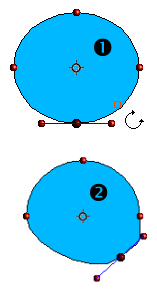 Figure 30: Moving a point on a curve. |
The Rotation function from the Effects drop-down button  on the Drawing Toolbar and the Rotation Mode after Clicking Object button on the Drawing Toolbar and the Rotation Mode after Clicking Object button  on the Options Toolbar can be used in Edit Point mode. In this case, it can be used to move single points around the contour of an object. on the Options Toolbar can be used in Edit Point mode. In this case, it can be used to move single points around the contour of an object.
Switch into Rotation mode by clicking on either of the rotation buttons. Notice that in rotation mode, all of the tangent points become red dots.
Select the point to be moved and then drag it around the contour while keeping the left mouse button pressed down (➊). When you let go of the mouse button, the point will be moved to the new position (➋).
If you move one of the handles located at the end of the tangents during rotation, you will make the object rotate in exactly the same way as with the usual rotation operations.
Important: To exit the effects mode, do not just single click on the effects button but single click the Select button  on the Draw toolbar. on the Draw toolbar.
|


