Editing gluepoints

From Apache OpenOffice Wiki
< Documentation‎ | OOoAuthors User Manual‎ | Draw Guide
Revision as of 02:43, 12 April 2008 by Jeanweber (Talk | contribs)

(diff) ← Older revision | Latest revision (diff) | Newer revision → (diff)
Jump to: navigation, search


Gluepoints can be edited using a separate toolbar (see Figure 13). This toolbar is context sensitive, that is it appears automatically when you click on the button Glue Point GluepointsIcon.png or select the menu command Edit > Glue Points.

The Glue points toolbar.
Figure 13: The Glue points toolbar.

The following briefly describes the function of each button on this toolbar.

NewGPIcon.png With this button you insert a new glue point.

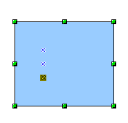
Draw a new object. If the object is filled you can place a glue point anywhere inside the object. With unfilled objects you can place a glue point only on the outside frame but after inserting it you can then drag it inside the object. Activate the Glue Points button on the Draw toolbar as described above.

DG-GPNew.png

The glue points remain visible as long as the button Glue Points is active. They appear as small blue crosses. A selected glue point has a gray square behind the cross. You can move a selected glue point with the mouse or delete it with the Del key.

DG-GP1Icon.png
DG-GP2Icon.png
DG-GP3Icon.png
DG-GP4Icon.png
With these four buttons you choose the connection “directions” which will be permitted for this glue point. You can choose one or more directions for a particular glue point. The directions specify the direction permitted for a connector to join to the glue point.

Activate Glue Points and then choose the direction. If for example you activate only the DG-GP4Icon.png button, every connector will be forced to come to the glue point from the left side of the point.

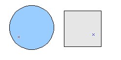
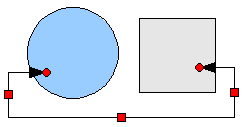
In the left drawing below is a glue point in the circle with a left entry and one in the square with a right entry. The effect of this is shown in the right drawing after adding a connector between the two glue points.

DG-GPHEx1.pngDG-GPHEx2.png

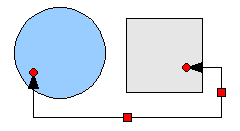
If you are in glue point editing mode and you add another direction to the glue point (for example by activating the DG-GP3Icon.png button), OOo will try to optimize the length of the connector. For the example above, the connection inside the circle would change as shown below:

DG-GPHEx3.png

DG-GPRelative.png If the Glue Point Relative button is active (it is active by default) the glue point will move when you change the size of the object, as shown below:

DG-GPRel1.pngDG-GPRel2.png

If the Glue Point Relative button is deactivated, the remaining buttons on the toolbar, previously grayed out, become active. With these buttons you can decide how a glue point will be placed when the size of the object is changed.
DG-GPH1.png
DG-GPH2.png
DG-GPH3.png
These buttons determine how the horizontal position of a glue point will change when you resize the object containing the glue point. The distance of the glue point to the left edge, vertical line through the middle, or the right edge will remain fixed when you change the size of the object. If the width of the object becomes less than the distance the glue point will be attach to the object frame.

The following example shows what happens when the object width is changed and the glue point is set to have a fixed distance to the left frame.

DG-GPHEx.png

DG-GPH4.png
DG-GPH5.png
DG-GPH6.png
These buttons determine in a similar manner the vertical position of a glue point when the size of the object is changed.


Content on this page is licensed under the Creative Common Attribution 3.0 license (CC-BY).
Personal tools