Difference between revisions of "Documentation/OOoAuthors User Manual/Draw Guide/Editing Pictures"
(→Practical Example: Changing wrong colors to transparency) |
(→Practical Example: Changing wrong colors to transparency) |
||
| Line 321: | Line 321: | ||
[[Image:EyeDropEx3.png]] | [[Image:EyeDropEx3.png]] | ||
| − | Now click on the icon [[Image:]], to change to the color selection mode. Outside the dialog the cursor changes to a hand. The field next to the icon shows the color immediately under the hand cursor. | + | Now click on the icon [[Image:EyedropIcon.png]], to change to the color selection mode. Outside the dialog the cursor changes to a hand. The field next to the icon shows the color immediately under the hand cursor. |
[[Image:EyeDropEx4.png]] | [[Image:EyeDropEx4.png]] | ||
Revision as of 09:00, 9 December 2007
Template:NeedsWork This is Chapter 6 of OpenOffice.org 2.x Draw Guide (second edition), produced by the OOoAuthors group. A PDF of this chapter is available from the OOoAuthors Guides page at OpenOffice.org.
<< User Manuals page
<< Draw Guide Table of Contents
<< Chapter 5 Combining Multiple Objects |
Chapter 7 >>
Contents
Introduction
Earlier chapters of the Draw Guide have dealt only with vector graphics. However, Draw also contains a number of functions for editing raster graphics (bitmaps)—for example, photos, scanned pictures, and so on—including import and and export as well as conversion from one format to another.
Draw can read in all the usual range of graphic file formats. It does not have the same capabilities as the specialized raster graphics programs like Adobe Photoshop or The Gimp.
Importing raster and vector graphics
You can import stored graphics files choosing Insert > Picture > From File on the main menu bar or by clicking on the ![]() icon on the Draw toolbar. In the list of supported data types are many different formats; OpenOffice possesses a suitable import filter for each one. The list includes both vector and raster graphic file types(1). If your data file has a nonstandard file extension, you will have to select the file and then explicitly choose the data type.
icon on the Draw toolbar. In the list of supported data types are many different formats; OpenOffice possesses a suitable import filter for each one. The list includes both vector and raster graphic file types(1). If your data file has a nonstandard file extension, you will have to select the file and then explicitly choose the data type.
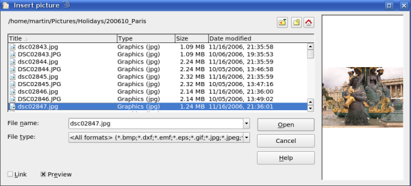
If you select the Preview checkbox in the Insert picture dialog (Figure 1), Draw shows a preview of the picture in the box on the right-hand side. This makes it much easier to choose the picture you want and you can see whether Draw can import a file of this format.
(1) An import filter for svg graphics is planned - more information can be found at http://wiki.services.openoffice.org/wiki/SVG_Import_Filter
To link or to embed?
Take careful note of the Link checkbox. When a graphic is linked, the graphic itself is not inserted into the document but rather a link to the graphic is created. This link is relative to the storage location of the document, even when it shows as an absolute link. If you store the document and the graphic in the same folder, and transport the folder as a whole to another computer, the graphic will show up in the document as before.
Linked graphics are not changed as a result of any actions carried out with OpenOffice.org. Any and all changes affect only the view of the graphic in the document and not the graphic itself. In particular the graphic’s format remains unaltered. A raster graphic is embedded in an OOo document as a PNG format image. Linking offers the advantage that the document size remains small; however, some actions do not last beyond the current session (for example Filter) or are simply not possible on a linked graphic (for example using the Eyedropper to exchange colors). If the picture is edited or even replaced by another, the link will still function. As long as the new picture is given the same name as the old one, links will be reestablished and updated when the document containing the link is next opened.
Links can easily be removed. The linked picture will then be embedded in the document. To break a link, choose Edit > Links from the main menu bar. In the Edit Links dialog (see Figure 2), choose the link to be broken and then click on the Break Link button.
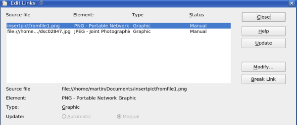
Figure 2: Editing links to documents
Scanning
With most scanners you can directly insert a picture in a document from the scanner. Click Insert > Picture > Scan and then either Select Source or Request.
The Select Source option opens a window which acts as an interface to a scanner device. Some scanner options can be directly set from within this window. See Figure 3.
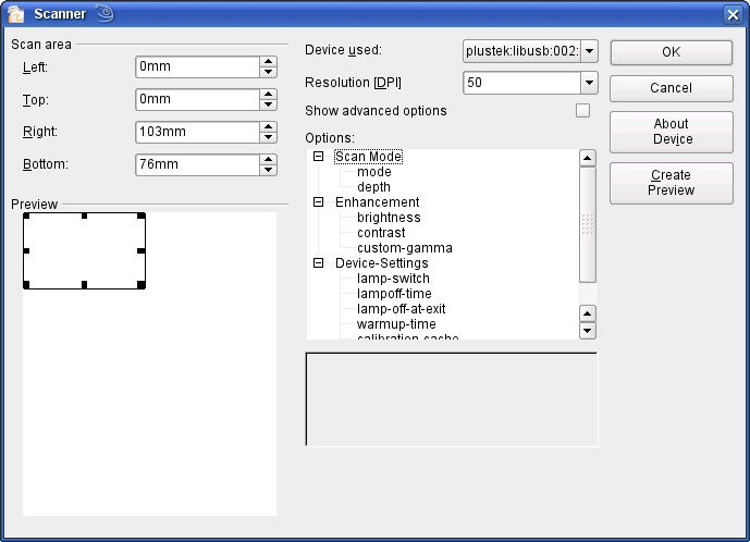
Figure 3: Select source ..... Scanner
Click on Create Preview to carry out a preview scan. The results are shown in the preview box on the left. Modify the scan area as desired and review the result as before. When you are satisfied with the scan preview output, click OK and then insert the scan into the document with Insert > Picture > Scan > Request.
Scanned images are embedded as a PNG format picture in the document.
Pasting from the clipboard
The clipboard offers another way to insert graphics. Depending on the source and the operating system, figures may be in different formats. You can obtain an overview by choosing Edit > Paste contents from the menu bar or by clicking on the small black triangle next to the Paste icon on the main toolbar.
Dragging and dropping
Drag and drop also functions in many situations. The exact way in which it works is not determined by whether the graphic is to be embedded or linked but rather the operating system in use and the source of the graphic. The behavior can often be controlled by the use of the Control or Control+Shift keys together.
Draw objects and images which are used frequently can be stored in the Gallery. Objects can be dragged from the Gallery to the Draw surface quite simply. Working with the Gallery is dealt with in detail in the section "Tailor made pictures" in Chapter 10 of this guide.
Inserting from a file
With this option complete pages or single objects from Draw or Impress documents can be inserted. In addition you can insert text in Rich Text Format (RTF), HTML format or plain text. The text will be contained in the Draw document within a text frame. The usual paragraph and character formatting options are available for this text.
Selecting Insert > from File brings up the File selection dialog. In Draw and Impress documents a special import dialog opens (see Figure 4).
Access to single pages or slides of the document can be gained by clicking on the + sign before the file name in the selection area. You can select whether to embed or link the selected page. If the name of the page or sheet already exists in the current document, you will be requested to give it a new name before it is inserted.
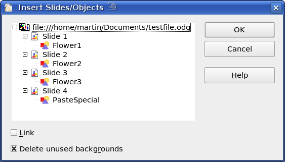
Figure 4: Inserting complete pages or objects on a page
Raster graphics (for example photos) and Metafiles are marked with a ![]() symbol, Drawing objects with a
symbol, Drawing objects with a ![]() symbol. Choose the object or objects (multiple selection using the Control or Shift key is possible). The inserted object keeps its original name, if it was named in the source document. Renaming an inserted object can be performed using the context menu and the entry Name. Renaming has the advantage that the object is then listed in the Navigator.
symbol. Choose the object or objects (multiple selection using the Control or Shift key is possible). The inserted object keeps its original name, if it was named in the source document. Renaming an inserted object can be performed using the context menu and the entry Name. Renaming has the advantage that the object is then listed in the Navigator.
Exporting graphics
Saving drawings in the native OpenOffice.org format (*.odg) means that (currently) in general only OOo (or StarOffice) users can open the files. To make it easier for other users and to use the drawings in other applications, you can export the graphics in other formats. Choose the command File > Export and then in the File format pull-down list select the desired format (see Figure 5).

Figure 5: Section of the file selection list
Exporting the entire file
The file format options in the upper area of the File format box—PDF, Flash and HTML—will result in the complete file being exported. Export in Flash or HTML format will result in each page of the Draw document being exported as a raster graphic. You will then not be able to access individual objects on the page. The Export Assistant can generate—if you choose—a Navigation aid to help in moving from page to page.
If you want to use the object(s) in other applications you would be better advised to select one of the Metafile formats (JPEG, PNG, TIFF, BMP etc) in the lower part of the File format list (see Figure 6). With this type of export only the currently active page is exported.
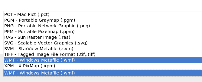
Figure 6: Lower part of the Export dialog
Exporting single objects
In order to export individual drawing objects you need to first select them. A selection can include more than one object. Take care to select the option Selection on the Export dialog.
Exporting as a vector graphic
The choice of vector formats is still limited. An export to a DXF format file (Autocad) is not possible. Even the export of a graphic to a SVG format file is not yet fully implemented: the graphic objects are exported as paths and 3D objects only as preview images. Best supported are the Metafile formats and exporting to one of these is usually successful.
Exporting as a raster graphic
The choice of formats for export as a raster graphic is large enough that you can always find one which will be supported by the application you wish to use. In case of any doubt, test out a number of the different formats to see which gives the best results; some programs behave differently depending on the format of the image to be imported into them.
After typing in a name for the exported file and selecting the file format you may be able to set options for the exported image—compression, color format, version of Metafile—depending on the format chosen. Some examples of the various option dialogs are shown in Figure 7.
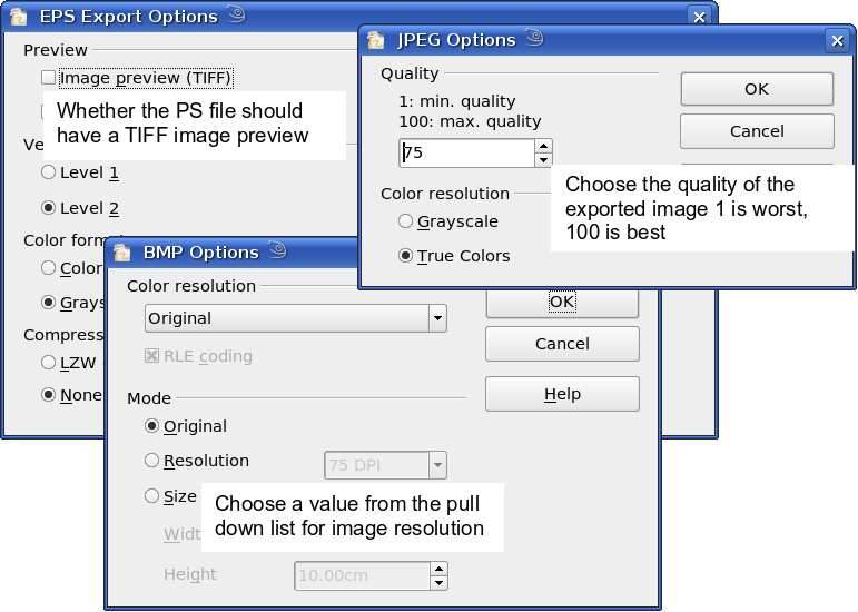
Figure 7: Adjusting format specific properties prior to export
In cases where the export dialog permits the input of the image resolution, note that this does not affect the number of raster points in the image. Rather it inserts into the picture information that informs other programs the dimensions to be used in displaying the image. This means that, among other things, missing raster points can be interpolated when the graphic is opened in the other program. The number of pixels used is determined by the screen resolution set up within the operating system and through the Drawing scale factor set in Tools > Options > OpenOffice.org Draw > General. This is a limitation of the current user interface; it is possible to set other resolutions using macros.
Embedded raster graphics, or objects which have been converted to a bitmap or Metafile (from the context menu Convert > To Bitmap / To Metafile) may subsequently be saved as a picture; from the context menu choose Save as Picture. In this way the picture is saved, but without Draw-specific additions such as text elements, borders, or shadows, and without the possibility of setting any of the options referred to above.
Draw objects can be exported into Writer, Calc or Impress documents without any problems. For objects used often this is most simply done by storing them in the Gallery or by using the clipboard. As Writer and Calc do not possess the same range of tools available within Draw, it makes sense to use Draw to produce a complex drawing and then to copy it into the other OOo application. A link to single drawing objects is not possible, but you can incorporate Draw documents in the other modules as linked OLE objects.
Modifying raster object properties
Like other objects, the properties of a raster graphic can also be modified. You can format the graphic using the Format menu or the context menu. The properties Lines, Areas and Shadows are adjusted using the Picture toolbar. The property Transparency in the Format menu does not relate to the transparency of the raster graphic itself but to the the background area. To set the transparency of the graphic you must use the Picture toolbar.
Graphics can also have a text element. More on text can be found in Chapter 10 (Advanced Draw Techniques).
In a manner analogous to that described for drawing objects in Chapter 3 of this guide, you can change the position and size as well as rotate graphics. Raster graphics can be mirrored (Modify > Mirror), but note that some Metafile formats might have problems with the mirroring of text. Graphics included as a member of a group behave like other drawing objects when the properties of the group are modified.
You should use the opportunity to (re-)name the graphic. Use the entry Name Object (under Windows this option is just Name) from the Modify menu or the context menu. Only named objects are visible in the Navigator and only named objects can be directly imported directly from another file.
View options
Graphics in the commonly used PNG and JPG file formats are stored in a compressed form and the file sizes are relatively small. If you wish to show one of these in a document it must be stored in an uncompressed form in the computer memory. This can lead to slow viewing times on systems with slower processors or less memory when your document includes many (compressed) graphics. OOo therefore offers the possibility to turn on and off the display of graphics.
The general settings are found under Tools > Options > OpenOffice.org Draw > View, in the section Alternative Display. While editing a document you can switch the display of graphics on and off using the Picture Placeholders icon ![]() on the Options toolbar. When the display of graphics is turned off, a thin frame, together with the name of the object (if it exists), is shown in place of the normal view (see Figure 8). In the preview of the page in the Pages pane, the graphic is shown as normal.
on the Options toolbar. When the display of graphics is turned off, a thin frame, together with the name of the object (if it exists), is shown in place of the normal view (see Figure 8). In the preview of the page in the Pages pane, the graphic is shown as normal.
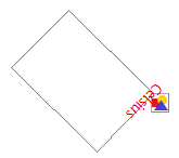
Figure 8: Placeholder view of a graphic
The picture (editing) toolbar
If you have enabled the Picture toolbar (in View > Toolbars) the toolbar will automatically appear on the screen whenever you select a (bitmap) picture (see Figure 9). It appears either directly under the menu bar in place of the formatting toolbar or as a floating toolbar on the screen.
The following table explains the individual functions on the Picture toolbar and illustrates their use with examples.
| Filter | This is a sub-toolbar and its function is described in The graphic filter toolbar. |
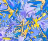
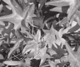
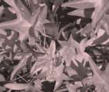
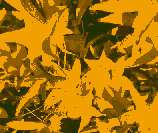
| Graphics Mode | Use the Graphics mode pull-down menu to change the display of the graphic from normal color to grayscale, black and white or as a watermark. This setting affects only the display and printing of the picture; the picture itself remains unchanged. |
| Default: | The graphic is displayed unaltered in color. |
| Grayscale: | The graphic is displayed in a grayscale: 256 shades of gray. |
| Black/White: | The graphic is displayed in black and white. |
| Watermark: | The brightness and contrast of the graphic are reduced to the extent that the graphic can be used as a watermark (background). |
| Color | Use the color tool to adjust the values of the three RGB colors, the brightness, contrast and the Gamma value. These adjustments do not affect the original picture but the values are stored in Draw as a separate formatting set. |

|
You can select values from between –100% (no color) to +100% (full intensity); 0% indicates the original value of the property. |
| |
The brightness can be adjusted between –100% (totally black) and +100% (totally white). |
| |
The contrast can be adjusted between –100% (minimum) and +100% (maximum). |
| |
The Gamma value affects the brightness of the middle color tones. Values can range from 0.10 (minimum) to 10 (maximum)
Hint: Try adjusting this value if changing brightness/contrast does not quite give you the result you want. |
| Transparency | The degree of transparency of the picture can be adjusted between 0% (opaque) and 100% (fully transparent). |
| Crop | Use this function to crop (trim) a graphic. If you click on this icon, a Crop dialog is opened (see Cropping below). |
| Line | Opens the Line dialog. In this context, line refers to the outline of the border (see also Chapter 4 of this guide). |
| Area | Opens the Area dialog. As usual you can edit color, gradient, hatching and fills, but here in the context of the background area which contains the graphic. To see the background, you must set the transparency of the graphic to a suitably high value. |
| Shadow | Use this tool to set a shadow effect around the graphic. |
Cropping
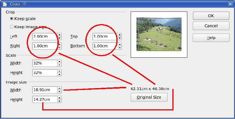
The fields Left, Right, Top, and Bottom establish the amount which will be trimmed off the appropriate edge. The new dimensions of the graphic are shown in the field Image Size. The dimensions are related to the original size of the graphic. In Figure 10 you can easily see that 3 cm from the sides and 2 cm from the top and bottom will be trimmed from the original object size. The preview pane shows the location of the new edges of the graphic.
- If you choose Keep Scale, the graphic will be cropped to the scales shown in the width and height boxes (in the above example both 32%) and the picture reduced in size accordingly.
- If you choose Keep image size, the graphic will be cropped and then enlarged to the original image size.
In addition to cropping you can also enlarge or reduce the size of the graphic by changing the percentage scaling values, or directly determine the size in the Image Size width and height boxes. Take care with these operations – in the Cropping dialog the width and height are treated as totally independent values. Changing one without the other can result in significant distortion of the image – this might not be what you want (the Position and Size dialog on the context menu has an option for keeping the width:height ratio fixed while changing one of the two dimensions). Changing values in one area (Scale or Image Size) will show up correspondingly in the other area.
The graphic filter toolbar
With the Filter tool (![]() icon) you can open the filter toolbar. Draw offers eleven filter effects. A filter works on the current view of an object and they can be combined. Filters always apply to the entire graphic – it is not possible to use filters to edit only a part of the object.
icon) you can open the filter toolbar. Draw offers eleven filter effects. A filter works on the current view of an object and they can be combined. Filters always apply to the entire graphic – it is not possible to use filters to edit only a part of the object.
If you have embedded the graphic in the document all filters will be applied directly on the embedded graphic. You cannot remove filtering applied to a picture. If you do not want to retain a filter you must use Edit > Undo to return to an earlier state of editing. After you save and close the document the filter effects are permanent.
Eyedropper
With the eyedropper you can change one color in a picture for another or set the the color as transparent. The tool works always on the entire picture; you cannot select only a region for editing.
The changes are carried out on the graphic itself. For this reason you cannot use the eyedropper tool on a linked graphic. If you try, you will receive the following message.
The tool can be used on all raster graphic formats and with many Metafile formats.
Practical Example: Changing wrong colors to transparency
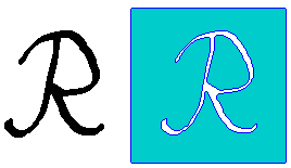
Some applications, which cannot correctly handle transparency, show transparent areas with the color Magenta and then store the graphic without the correct transparency information with this color.
| |
|
Bitmap graphic with area in magenta, which actually should be shown transparent. On the left is the original picture, right is the picture after saving it with MS Paint. |
If you receive such a picture, you can recreate the transparency with the eyedropper tool.
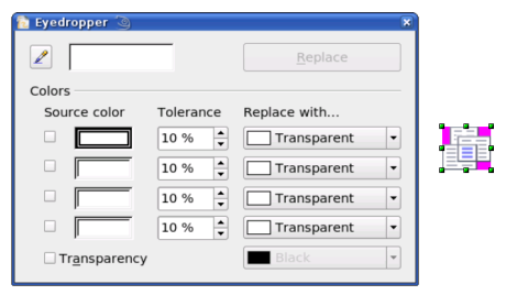
Open the Eyedropper dialog with Tools > Eyedropper and click on the picture to be edited.
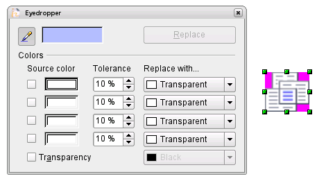
Now click on the icon ![]() , to change to the color selection mode. Outside the dialog the cursor changes to a hand. The field next to the icon shows the color immediately under the hand cursor.
, to change to the color selection mode. Outside the dialog the cursor changes to a hand. The field next to the icon shows the color immediately under the hand cursor.
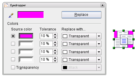
Click on the color to be changed. The first Source Color box is now marked and the color selected appears in the left box. In the Replace with selection list, the option Transparent is already selected. You can then click on the Replace button at the top right of the box to carry out the changes to the picture. There is no preview of the effect. If the result is not what you wanted, choose Edit > Undo.
The dialog does not close automatically, so you can carry out further color replacements. Mark first the field for the Source color and choose again the color with the eyedropper. Close the dialog with Ctrl-F4 or the close icon on the window border. Draw uses an Alpha channel for transparency so that pixels of different colors can be made transparent.
It is also possible to carry out the operation in reverse. to change a transparent area to a color. For this process, select nothing in the graphic but mark the Transparency checkbox at the lower left of the dialog and at lower right select the color to replace areas which are currently transparent.
The selection list for replacement colors shows all the available colors in the current color palette of the document. You cannot define any new colors here but you can add colors to the available palette before using the eyedropper tool. More on this topic is contained in Chapter 8 (Tips and Tricks).
Effect of the ‘Tolerance’ parameter
The tolerance parameter describes how exactly a color value in the picture must agree with the source color, in order to be replaced. In the figure the red color tone at the left edge of the color palette was input and a pure blue chosen as the replacement color. The original is a rectangle with color palette from red to green. Because the eyedropper is not usable on drawings, the rectangle on the left side was converted into a raster graphic (Convert > Bitmap). The picture was then exported in a Enhanced Metafile format and again inserted.
Color Depth
In OOo 1.1 the context menu contained a submenu Color resolution. This is no longer available in version 2 although the individual commands still exist. If you want to have all these commands available you should generate a separate menu (refer to OOo help if you are not sure how to do this). For most of these commands there is no icon available and generating a separate toolbar is probably not worthwhile.
To find the tools, click on Tools > Customize, Toolbars, and Add (Command). The commands are in the category Modify, at the top of the list.
Reducing color depth
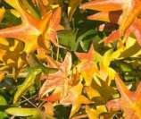
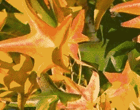
| File:Depth1.png | Original with a 24 bit pixel depth (=8 bits per channel) |
|
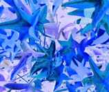
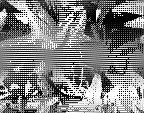
1 bit dithered
The impression of grayscale is produced by a raster. Actually there are only 2 colors. |
|
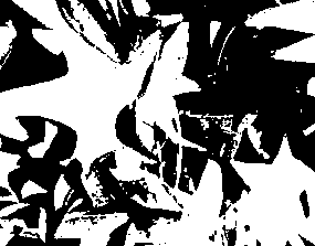
1bit threshold
You cannot directly set the threshold value. With the help of the color tool on the Picture toolbar you can influence which part of the image is set to black (vary color settings—red, green, blue level, brightness, contrast and/or gamma value—to see what works best for your image). To do this you must first export and save the modified image with File > Export and then reopen it, before you finally change the color depth. |
|
4bit color palette
With 4 bits a total of 16 colors can be produced. The color steps are quite fine, because the process uses not the 16 RGB basic colors, but selects those from the palette which best match the colors in the image. |
|
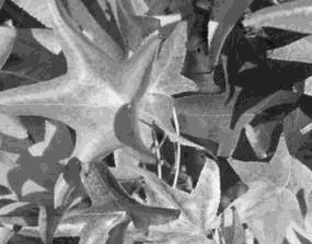
4bit grayscale palette |
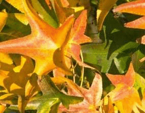
|
8bit color palette
With 8 bits a total of 256 colors can be produced. The image at left is at first glance very difficult to distinguish from the original. A big difference is that the picture is only one third of the size of the 24 bit version. |
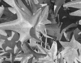
|
8bit grayscale palette |
Conversion
Convert to a contoured image
Select the picture so that you see the green handles. From the context menu or from the Modify menu choose Convert > to Contour. This command creates from the original image a polygon or group of polygons, with 4 corner points and the image set as a background graphic. In this state you are not able to further edit the graphic. All your modifications must be completed before this point.
The polygon is in fact a vector graphic but the picture remains as a bitmap image. The polygon offers you in any case a number of possibilities for further change: modify shape or define transparency gradient.
Convert to a polygon
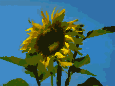
Select the picture so that you see the green handles. From the context menu or from the Modify menu, choose Convert > to Polygon. This command creates, from areas of the same color, a number of small polygons filled with color. The total image effectively becomes a vector graphic and can be resized with no loss of image quality. The resulting format will be a Metafile.
The conversion begins with the Convert to Polygon dialog, where a number of settings can be defined. The Preview button generates a preview of the conversion with the current settings. Because graphics conversion can take some time, depending on the picture and the computer, a progress bar is included at the bottom of the dialog (see Figure 11).
Conversion of a picture to polygons
Figure 11: Conversion of a picture to polygons
Number of colors
Draw considers between 8 and 32 colors in the conversion. The picture can, however, contain fewer colors. For every color occurring in the picture, Draw creates a polygon; the polygon may in fact consist of several disconnected parts. These polygons are then filled with the relevant color.
The algorithm used in the reduction of the number of colors is not yet optimal. It is worthwhile to try reducing the number of colors by changing the color depth or with the Poster filter.
Point reduction
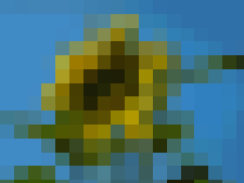
Polygons will only be created if they have a size greater than the value given in this setting. The section of the picture below, highly magnified, shows that with a larger point count small flecks of color—typical of irregular color patterns—simply disappear.
Fill holes
Point reduction can result in small areas or “holes” which are not covered by a polygon. If the Fill holes option is marked, additional square, tiled areas are created with a background color the same as the hole. The Tile size option allows the width in pixels of the width of these square areas to be preset.
If you next split the existing Metafile (Modify > Split), access is gained to individual polygons. To be able to operate on these together you should immediately group them after splitting.
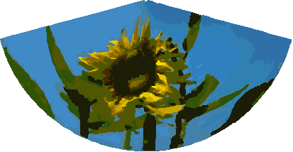
With such a vectorized form of the image you can now carry out operations which you would know from classic drawing programs. It is possible for example to carry out a curved warping operation. For transformations like this it is much less effort to use a conversion with background tiles, because then the edges of the picture are straight.
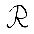
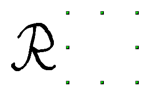
To use this tool to vectorize the first letter of a chapter in a special font, set the color depth to 1 bit and do not use any background tiling. An example is shown below.
Convert to bitmap
With the command Convert > To Bitmap from the context menu you can convert a vector graphic (all drawing objects are vector graphics) to a raster graphic. Draw creates a raster graphic in PNG format with a color depth of 24 bits. Any transparency effects which were created in the vector graphic are unfortunately lost in this conversion, although the PNG format used in Draw does support transparency. Only if you use the eyedropper tool to set transparency will an Alpha channel also be produced.
To determine the number of pixels required, Draw considers the dpi setting of the operating system for the screen and the percentage scaling factor set under Tools > Options > OpenOffice.org > View in the section User Interface.
Example:
Width of vector graphic: 1.5 inch Monitor setting of operating system: 96 dpi ( = 96 dots per inch) Scaling 130 %
Calculation: 1.5 inch x 96 dpi *130% = 187 pixels
The actual number of pixels will vary somewhat from this value due to rounding. When the format permits, Draw uses a dpi value (in this case 125 dpi) which permits the calculation to be reversed and the picture with this pixel value reproduced with the correct width of 1.5 inch.
Print options with raster graphics
If you have a black and white printer or are experiencing problems with printing you should have a look at the following settings.
You can set up printing so that all text and all graphics are printed in grayscale or black and white. The general settings are found in Tools > Options > OpenOffice.org Draw > Print in the section Quality. The same settings may be set for the current document only under Options in the Print dialog (File > Print). With both Black & White printing and Grayscale printing no background is printed.
Other options can be found under Tools > Options > OpenOffice.org Draw > Print. They relate to page options (scaling) and other printing variables. They will have an effect on the size of the print file and the time taken to print the document. With most modern systems you can simply accept the defaults. As different operating systems and printers have their own requirements, you will need to tailor the settings to your particular site conditions. Refer to the individual sections of the Help file for more information.
| Content on this page is licensed under the Creative Common Attribution 3.0 license (CC-BY). |
