Drawing to scale
Draw is not a CAD program but a graphics program with which you can produce drawings to a scale. The example used for this chapter is a drawing of a Logic Circuit Diagram. The exact meaning of the individual symbols is not described here as we are only interested in the drawing techniques used to produce the diagram.
The logic symbols in Figure 1 form the building block library for our scale drawing.
Working with Position and Size
So that the edges of the building block symbols do not coincide with the wiring, they should be 8 mm wide and 8 mm high. The connections to the symbols should have a length and separation of at least 5 mm. These values are all random values and you would normally substitute values that suit your own needs.
For the drawing surface a measurement unit of millimeters, a grid spacing of 5 mm, and a grid subdivision of 4 points were used. In addition you should probably activate Display grid and Guides when moving as well as Snap to grid (see Chapter 8 of this guide). This drawing will serve later as a collection of available symbols and you should not only draw the symbols but fully detail them as well.
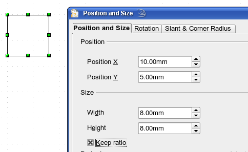
The first step is to draw a base element, an AND gate block. You can then dimension and detail this element (use the Position and Size dialog, as shown in Figure 2; double-click on the status bar or context menu to help with dimensioning). For this example, the left upper corner of the block is at x=10 mm and y=5 mm.
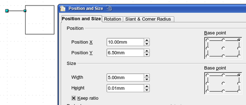
Draw the first connection lead by eye and dimension and position it using the Position and Size dialog (Figure 3).
Use the same method to draw the remaining two leads. For positioning the input leads, fix the right end points; for the output lead, fix the left one. The first wire lies 1.5 mm below the upper edge of the block. The leads have a 5 mm spacing between them. The following table shows the relevant coordinates of the upper corner points and the leads.
| left (X/Y) [mm] | right (X/Y) [mm] | Input 1 (X/Y) [mm] | Output (X/Y) [mm] |
| 10 / 5 | 18 / 5 | 10 / 6.5 (right EP.) | 18 / 6.5 (left EP.) |
For the lower input lead, increase the Y coordinate of Input 1 by 5 mm to 11.5.
The AND gate block is almost finished and we can use it as the basis for all the other gates. So that the drawing gives a good visual impression, use the Duplicate command from the Edit menu to ensure uniformity of shape and size.
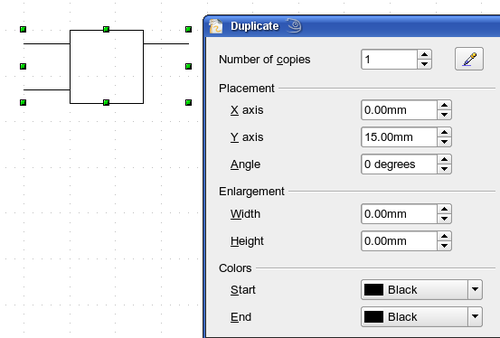
Because we want to copy the block vertically downwards, use a Placement on the X Axis of 0 mm and on the Y Axis 15 mm (see Figure 4).
With the same method, copy both blocks twice more to the right. Select both blocks, call up the Duplicate dialog, and use placement values of 30 mm (X) and 0 mm (Y). Your drawing should look similar to Figure 5.
For the INVERTER or NOT gate the connection leads must be amended. Move one input and one output lead to the middle of the block and delete the superfluous input lead.
Draw the missing circle for negation with a diameter of 2 mm, place it by eye in the center and then position it and dimension the connections from the Position and Size dialog as described above.
You can copy the circle to the Clipboard and then paste it as many times as you need, positioning it and adjusting the lead lengths as above.
A wiring diagram also needs a symbol to show a connection point. Draw a filled circle for this.
Next add text to the symbols (&, =1 etc.). Activate the icon [[Image:]] on the Options Toolbar. Double-clicking a symbol will now put you in a special text input mode. This integrates the text as an element in the object (see also Chapter 2 of this guide). You will find the OR symbol (≤) in the list of special characters (Insert > Special Characters).
It is probably a good idea to create a group for each type of gate. This will make it easier to use them in a diagram. Your diagram should now resemble Figure 1; save it to disk.
If you want you can add a name to each of the gate symbols (AND, OR ..), use a separate layer to add this text so that you can switch it off when necessary.
You can place glue points at the end of each connection lead. This will simplify the actual “wiring up” later when you add in the connectors.
Setting glue points
This instruction assumes a basic knowledge of connectors and glue points. For additional information refer to Chapter 2, Chapter 8, and Chapter 9 of this Guide.
| If objects are included in a group it is not possible to add glue points to them. Glue points must be set before any grouping is done. |
Unfortunately you cannot set the position of glue points using numerical values. It is necessary that the glue points on the connection leads are placed exactly on the end of the line (otherwise the wires will not be properly aligned).
The best solution is to work with the Zoom toolbar. You can find this as a tearoff toolbar on the standard Draw toolbar. It contains (among others) tools for zooming in and for zooming out (enlarging the view/making the view smaller) of the current view. If you click on the Zoom In tool and then click on the page, the scale is doubled and the view centered on the place where you clicked.
As the ends of the connection leads in this example do not lie on grid points, you must switch off Snap to Grid and activate Snap to Object Points.
When you have done this you can open the Glue Points toolbar with the Insert Glue Point icon [[Image:]] on the main Draw toolbar or using View > Toolbars from the menu bar.
Select the block on which you want to insert a glue point. Click the Insert Glue Point icon [[Image:]]. It is now activated and appears with a lighter background. The mouse cursor changes to a small cross and you can set the first glue point. Click the mouse at the desired location. If the point is not exactly where you want it, move it by dragging with the mouse.
When you are satisfied with the location, click on the Glue Points toolbar on the icon with the Exit Direction you want (left, right, top or bottom). The icon you click will be shown with a lighter background. Set the exit direction of the input connection leads to the left and the output leads to the right.
When you have set a glue point at the end of each gate’s connection lead, you can copy it into the Gallery.
Copying individual pictures to the Gallery
The Gallery is a very convenient way of controlling drawing building blocks. It also functions as a symbol library.
First open the Gallery using the menu command Tools > Gallery or by clicking on the ![]() icon if it is present in one of the toolbars.
icon if it is present in one of the toolbars.
The Gallery appears above the drawing page. The left pane shows the folders available for use and the right pane shows the images contained in the current folder. Choose an image by clicking on it; additional information about the image appears in the header bar.
In the left pane, click the New Theme button to create a new folder. A new window opens. Click on the General tab and give the new theme a meaningful name (for example Logic) to replace the default of New Theme. You can rename a theme by right-clicking it in the folders pane on the left.
To import existing images into the Gallery, click on the Files tab and then on the Find Files... button. It is possible to bring in complete folders or individual files; the procedure is self-evident from the dialog windows that open, or see Chapter 14 (Working with the Gallery) in the Getting Started guide.
You can drag and drop Draw objects straight into the Gallery. The Properties window can be closed after typing in the name. First select the destination folder, then click on the first symbol that you wish to add to the Gallery. Position the mouse cursor inside the selection frame of the symbol. When the crossed arrows are visible, click on the symbol and keep the mouse button pressed. After about 1-2 seconds or so the cursor will briefly blink and change to the drag symbol. Drag the object into the Gallery and release the mouse button. When you move the mouse into the Gallery field, the cursor shape changes once more (see Figure 7).
| Tip | Zoom in on very small graphics before you try to move them so that the crossed arrow symbol can be clearly seen. |
When you have placed all the symbols in the Gallery they can be titled. Right-click on a symbol, choose Title from the menu and type in the symbol name (AND, OR).
The symbol library is available to all OO modules, at least for users who have the permission/rights to access it. Making available the drawing collection as a Draw file is the simplest way to distribute a symbol library to other users. After opening the drawing, other users can easily transfer the drawing objects into their own Gallery, as described above.
| Content on this page is licensed under the Creative Common Attribution 3.0 license (CC-BY). |


