Dimensioning a drawing
Configuring the dimensioning template
As is usual with OOo, you carry out the configuration of dimensioning using its own style format.
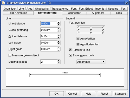
After opening a drawing, press F11 to access this style and select Dimension Line. To see the style details, right-click on the style Dimension Line and select Modify. The dialog that opens contains the current settings. Click the Dimensioning tab (Figure 14).
You can configure all the properties you see in this window to suit your own needs. The left section includes the basic settings for dimension lines and dimension guide lines (these indicate where on the object the dimension is referenced):
Line distance: the distance of the dimension arrow from the object edge
Guide overhang: the distance the guide line extends past the arrow
Guide distance: the distance of the guide line from the object edge
You can individually set the line lengths of the right and left guide lines and use positive or negative values to have the line above or below the reference point. The direction of the line with positive or negative distances depends on the setting of the Measure below object option (box checked or not), but this is easy to check by referring to the example dimension line in the bottom window of the dialog.
In the right section you can change the settings for the Legend, the text of the dimension line. You can use the Text position choices to change the location of the text – but only if one or both of the AutoVertical and AutoHorizontal checkboxes are unchecked. Use the various options on the Text and Alignment tabs to further change the text format.
Calculation of dimensions always takes into account the scale and dimension units contained in Tools > Options > Draw > General. If you set a scale of 1:10 and a unit of centimeter, then a 6 cm long object in the drawing will be shown with a dimension of 60 cm when the option Show meas. unit is activated and the selection window set to Automatic. Deselecting this option turns off the display of units. You can change the units displayed from Centimeters to (for example) Millimeters by choosing Millimeter instead of Automatic in the selection window.
Adjust the font type and size for the text of a dimension line by means of the Text tab.
The Standard button at the bottom of the dialog sets all the properties of the dimension line to the (inherited) standard properties of the style.
Dimensioning Objects
In this exercise you will dimension some logic blocks (see Figure 15). They are used here to demonstrate the technique; you can use your own drawing or fetch a picture from the Gallery.
So that Draw can clearly recognize the edges to be measured, you should set a number of guide lines delineating the edges. The previous sections explain how to do this. To place the guide lines exactly and easily, change the resolution of the Grid. Suitable values for this work are a resolution of 5 mm and a subdivision of 4 points. With this setting you should have a snap to grid function with 1 mm point separation.
We will begin by dimensioning the NOT gate. For this block we want the total width (18 mm) and the width of the block itself (8 mm) to have dimension lines. The first step is to add guide lines to delimit the dimension lines. With Snap to grid activated you can position these quite accurately (see Figure 16a). Watch that the function Snap to guide lines is active and zoom in to the part of the block to be dimensioned. The block should not be selected.
Start the dimensioning command by clicking the Dimension Line icon [[Image:]] on the Lines and Arrows dialog. The dimension line is placed automatically on the Dimension Lines layer so you can hide the dimension lines if you wish.
After clicking the Dimension Line icon, the mouse cursor changes into a small cross. As we activated the option Dimension Line – Measure below Object, the dimensioning should be made in a counter clockwise direction. Place the mouse cursor at the left dimensioning point. Press the left mouse button and drag the mouse to the right dimensioning point. Release the mouse button. If you press the Shift key while dragging the mouse, you will restrain the dimensioning line in a horizontal (or vertical) direction (see Figure 16 b).
In the same way you can draw a vertical dimension line on the AND gate. The dimensioning of the NEGATION symbol should also be simple to accomplish, but it is important that for such small components you zoom in enough to accurately position the lines.
Editing dimension lines
Dimension lines can be subsequently edited. You can select single dimension lines which are displayed with four handles, located at the end of the dimension lines (Figure 17).
With the upper handles you can (only) change the length of the guide lines. With the lower handles you can move the points that are being dimensioned. If you select the dimension text, you can edit the font type and size as well as changing the dimension units of the text.
If you only want to edit the text of the dimension, double-click on an unselected dimension line to enter text edit mode.
All the changes that you make related only to the selected dimension line. They are stored and persistent, but do not affect the settings of the Dimension Line style. If you insert other dimension lines, they will have the settings contained in the style template.
If you want to make general setting changes to the Dimension Lines style, change the appropriate style template. As soon as you confirm the changes with OK, the new settings will be applied to all dimension lines.
| Content on this page is licensed under the Creative Common Attribution 3.0 license (CC-BY). |


