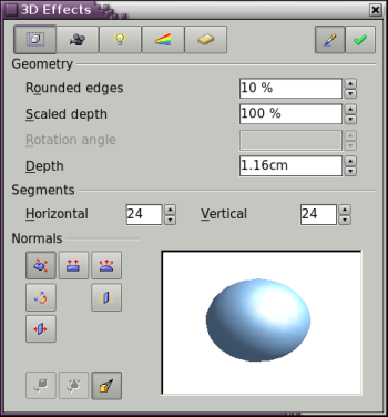
Dialog page - Geometry
- Creating 3D objects
- Creating 3D bodies
- Producing 3D shapes
- Editing 3D objects
- 3D settings for 3D bodies
- Dialog page - Geometry
- Dialog page - Shading
- Dialog page - Illumination
- Dialog page - Textures
- Dialog page - Material
- 3D settings for 3D shapes
- Combining objects in 3D scenes
- Examples for your own experiments
On this page (see Figure 14) you can make changes to the geometry of a 3D object. This page is opened with the Geometry button ![]() in the upper part of the 3D Effects dialog.
in the upper part of the 3D Effects dialog.
In the first example, the depth (length) of a body is to be changed. This only makes sense if you created it through extrusion. Draw a circle and convert it according to variation 1 above into a 3D object (a flat cylinder) – see Figure 15 a and b.
If necessary, select the cylinder, change the parameter Depth to 3.5cm and click on the Assign icon ![]() . The cylinder should now resemble the figure in Figure 15 c.
. The cylinder should now resemble the figure in Figure 15 c.
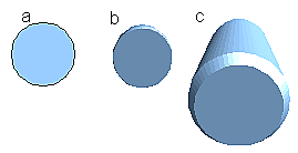
Figure 15: Conversion of a 2D object (a) into a 3D object (b) and then changing its depth (c)
This parameter cannot be applied to a rotation body or one of the ready made 3D objects.
With the parameter Rounding you can specify how strongly the edges of the 3D object are rounded. Select (if necessary) the lengthened cylinder again and change the rounding to 30%. The cylinder should now resemble that in Figure 16.
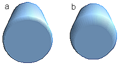
Figure 16: Edge rounding of 0% (a) and 30% (b)
This parameter is also interesting if you convert text into a 3D object. The rounding process works also on objects which have been extruded.
The parameter Scaled Depth sets the ratio of the size of the front to that of the back of a 3D object produced using extrusion. The front side of a 3D object produced by extrusion always protrudes out from the original surface – the rear side is the original surface of the 2D object, that is the 2D exit surface, even if the object has in the meantime been rotated.
By default the scaling is set to 100%, which results in both surfaces being scaled by the same amount. If you set this scaling to 50% the cylinder becomes the frustrum of a cone (see Figure 17).
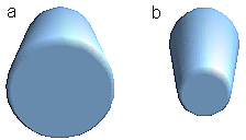
Figure 17: Cylinder with 50% scaling
The diameter of the front side is 50% that of the corresponding rear side. It is of course also possible to create the reverse effect, with the rear side smaller than the front side, by using a value of scaling depth greater than 100%.
With rotation bodies this parameter influences the width of the surface parallel to the axis of rotation. At the end of the rotation the surface width is the figure given by the scaling depth. The distance to the rotation axis remains unchanged. In Figure 18 a line is rotated to create a 3D object with a scaling depth figure of 0%.
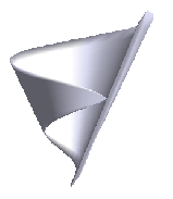
Figure 18: Scaling depth of a rotation body
The parameter Rotation Angle is only available for rotation bodies. With this parameter you can create a segment of a complete rotation body by choosing an angle less than 360 degrees. Figure 19 shows a hemisphere with a rotation angle of 270°.
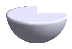
Figure 19: Hemisphere with a rotation angle of 270°
The parameters Horizontal and Vertical Segments define the number of segments out of which Draw builds spheres and rotation objects[1]. With rotation objects the horizontal segments are of more importance. The vertical segments have an influence on the degree of edge rounding.
In Figure 20 the left sphere is made up from 10 horizontal and vertical segments while the right sphere has 25 segments. The more segments you choose the smoother the surface will be but it will take longer to generate the figure on the screen. By default spheres and hemispheres are constructed with 24 segments. For a square pyramid you need four horizontal segments.
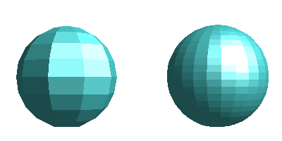
Figure 20: Sphere from 10 segments (left) and 25 segments (right)
These are properties belonging to individual objects. If you use the setting for segments on a 3D scene, all the objects contained in the scene are modified accordingly.
If you extrude an unfilled circle or intersecting lines with a filling the result is probably not what you expect. In this case the Double-Sided ![]() tool, on the lower part of the dialog page, may be able to help. The effect becomes clear when one changes the line properties of an object from invisible to continuous and so enables all edges to be seen. Otherwise it may happen that some surfaces receive no filling (see Figure 21). For lines without filling the effect is switched on by default and cannot be switched off. This is also a property of single objects.
tool, on the lower part of the dialog page, may be able to help. The effect becomes clear when one changes the line properties of an object from invisible to continuous and so enables all edges to be seen. Otherwise it may happen that some surfaces receive no filling (see Figure 21). For lines without filling the effect is switched on by default and cannot be switched off. This is also a property of single objects.
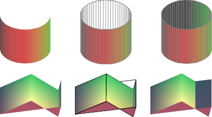
Figure 21: Left: without "Double-Sided"
Middle: with continuous lines but without "Double-Sided"
Right: with "Double-Sided"
Use the buttons in the section Normals to modify the normals of a 3D object.
A Normal is a straight line which is perpendicular to the surface of an object (in the same way that a vector, starting from inner and extending outwards, is at right angles to the surface of the object at the point where it exits. Figure 22 shows some normals extending outwards from a sphere made up of 10 segments.
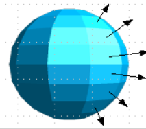
Figure 22: Normals (vectors) of a 3D sphere with 10 segments
Using normals the display of the object surface and the variation in colors, textures and lighting can be controlled. You can thus influence directly how the surface of the object is rendered.
The three icons in the first row work as “Either-Or” switches. Only one of the effects can be active at a given time – an effect can be switched off by clicking on one of the other icons.
The setting is associated with an individual object – every object can have its own setting. The rest of the icons are “normal” On-Off switches. The following effects are available:
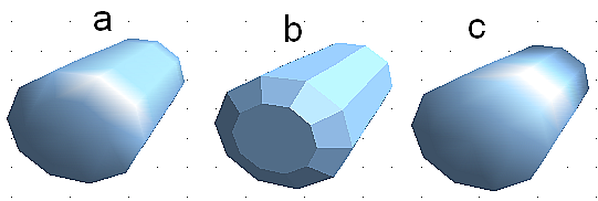
Figure 23: Cylinder with 10 segments a= Object-specific b=Flat, c=Spherical
The following table shows the linkage between Double sided illumination and Invert Normals.
| The light source is on the right. | Normals not inverted | Normals inverted |
| No double-sided illumination | 
|

|
| With double-sided illumination | 
|

|
| Content on this page is licensed under the Creative Common Attribution 3.0 license (CC-BY). |
Cite error: <ref> tags exist, but no <references/> tag was found
