Creating lines and shapes
- The Drawing toolbar
- Creating lines and shapes
- Working with 3D shapes
- Grouping shapes together
- Arranging shapes
- Flipping shapes
- Aligning shapes
- Alignment using the grid and snap guides
- Converting an object to a different type
- Setting up interaction with a shape or image
- Animating images
- Using Fontwork
To create shapes and lines:
- Select the desired line or shape tool.
- Click and drag to create the object on the slide.
Creating a shape.

When drawing a polygon, keep the Shift key pressed to restrict the angle between the segments to multiples of 45 degrees. To finish drawing a polygon, double-click on the last part of the segment. If a closed polygon was selected, OOo will color the inside area.
When drawing certain shapes, one or more yellow dots are displayed along with the blue resizing handles. These dots perform a different function according to the shape they are applied to. With the basic shapes the yellow dot (or dots) are used for the following purposes:
- Rounded rectangle and Rounded square shapes: use the yellow dot to change the size of the curve replacing the corners.
- Circle Pie: use the two yellow dots to change the size of the filled sector.
- Isosceles triangle: move the yellow dot on one vertex to modify the triangle type.
- Trapezoid, Parallelogram, or Octagon: move the yellow dot to change the angle between the sides.
- Cross: use the yellow dot to change the thickness of the four sides.
- Ring: use the yellow dot to change the internal diameter.
- Block arc: use the yellow dot to change both the internal diameter and the size of the filled area.
- Cylinder and Cube: use the yellow dot to change the perspective.
- Folded corner: use the yellow dot to change the size of the corner.
- Frame: use the yellow dot to change the internal rectangle diagonal.
Working with connectors
Connectors are lines that can be anchored to particular places, called glue points, on the graphic object. The advantage of connectors is that when the graphic object to which the connector is attached is moved or resized, the connector automatically adjusts to the change. When creating a flowchart, organization chart, schematics or diagrams, it is highly recommended to use connectors instead of simple lines.
Impress offers a wide variety of predefined connectors, which differ in the termination shape (none, arrow, custom) and in the way the connector is drawn (straight, line, curved). See Connectors options on the Drawing toolbar.
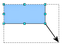
Unlike normal lines, when a connector is drawn or selected Impress displays red handles; in particular, the termination points are identified by red circles, while square handles are used to modify the routing of a connector (where applicable).
Draw a connector in a similar way to drawing any object. First select the connector style from the Connector toolbar, then move the mouse cursor over one of the objects to be connected. When the cursor is brought near an object, small black crosses appear around the object; these represent the glue points to which the connector can be attached. Click on the required glue point to attach one end of the connector, then hold the mouse button down and drag the connector to the second object and click on a glue point on that object to connect the other end.
For instructions on how to format a connector, refer to the corresponding section in Chapter 6 (Formatting Graphic Objects).
Managing glue points
As described above, a glue point is the point of attachment for a connector to a shape or graphic object. Each shape has a number of predefined glue points, but it is possible to define new ones as well as edit them, using the Gluepoints toolbar, shown below.
-
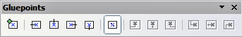
The Gluepoints Toolbar.

Use the first tool to insert a new glue point. The next four tools determine the exit direction of the connector terminating at the glue point. To maintain the relative position of the glue point when resizing the object, make sure that the Glue point relative icon (highlighted in the figure above) is selected. Deselecting the Glue point relative icon enables the next six icons of the toolbar; use these to fix the position of the gluepoint during the resizing of the object. Hover the mouse over the buttons to obtain a tooltip giving a short description of its function.
To delete a custom glue point, select it with the mouse and press the Delete key.
Setting custom glue points is particularly useful where multiple connectors terminate on the same side of a shape or where the default glue point position is not satisfactory.
To move a predefined or newly inserted glue point:
- Select the glue point tool from the Drawing toolbar.
- Click on the glue point you want to move. The glue point should now be highlighted.
- Keep the mouse button pressed and drag the glue point to the desired position. Release the mouse button.
| Glue points are placed by default on the grid (see Alignment using the grid and snap guides for information), however it is sometimes required to fine tune the position of the glue point depending on the shape. To do this, keep the Control key pressed while dragging the glue point to the new position. |
| Content on this page is licensed under the Creative Common Attribution 3.0 license (CC-BY). |